Francisco Torrent-Guasp
VENTRICULAR MYOCARDIAL BAND - FORM
![]()
![]()
![]()
![]()
|
|
Francisco Torrent-Guasp VENTRICULAR MYOCARDIAL BAND - FORM |
|
|
|
|
To see the figures bellow enlarged, please just click on the figure´s miniature.
To come back again, please press "BACK" button on your browser. |
"With what words, o writer, will you describe with like perfection the entire configuration which the drawing here does? But I council you not to encumber yourself with words unless speaking to the blind. The longer you write on the details the more you will confuse the mind of the auditor.”
Leonardo da Vinci You may download this lecture as Adobe Acrobat PDF file (372 KB) following the link bellow. Ventricular Myocardial Band - Form
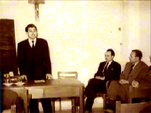
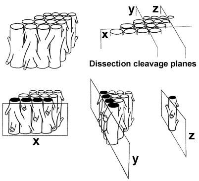
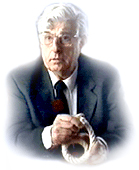
VENTRICULAR MYOCARDIAL BAND - PREFACEBeing a 4th year medical student (Figure 1), my interest in heart structure led me into a series of maroscopical studies of the ventricular myocardium, which have enabled me, 25 years later, to lay down, in a coherent and comprehensive survey, the morphological basis of myocardial function. To make these results more accessible to any reader, I must first comment on the vocabulary generally used in morphology and on the one used in my descriptions. When speaking about fibres and layers, we must keep in mind that, in macroscopical dissections, these morphological units are not precisely definable. As these units are dissected, it only means that a myocardial mass, bigger (layer) or smaller (fibre), is arbitrarily separated from the whole. When any part of the myocardial body is manually isolated, it only has a single constant characteristic in all hearts - it's preferential direction, that I call "linear pathway or trajectory", when referring to fibre, or "laminar pathway or trajectory", when referring to layer (Figure 2). These muscular pathways, or trajectories - linear and laminar - usually identified as sliding planes (plans de cleavage or planos de deslizamiento), are infinite, since their size, and morphological characteristics, depends on the dimensions of the muscular mass selected by dissection. It is, therefore, not possible to define or to isolate identical fibres or layers in two hearts. In blunt dissections only the preferential pathway - linear trajectory or laminar trajectory - is constant at any site in the ventricular wall. That is why it can be said that the myocardial unit has a functional identity rather than a morphological one, since the function of any muscle (contractile linkage between two points) depends on the direction of its longitudinal axis, i.e., on the disposition in the space of its preferential pathway, of it’s trajectory. In support to this, I will cite a sentence from, widely cited D.D.Streeter’s seminal work*, although very few of those who are quoting this paper know that it was, actually based on my anatomical dissections and studies (Figure 3):
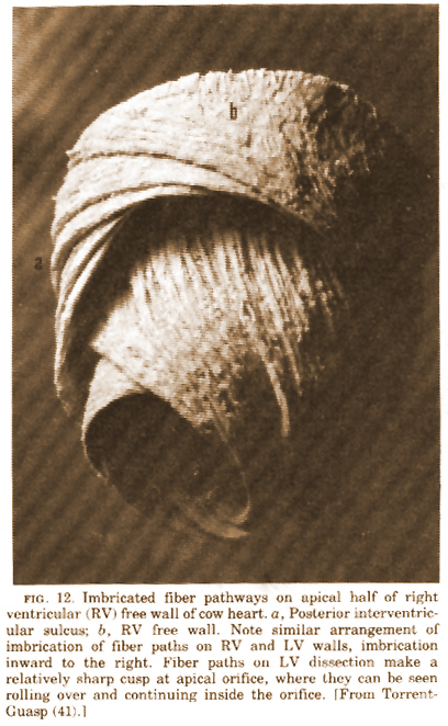
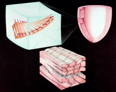
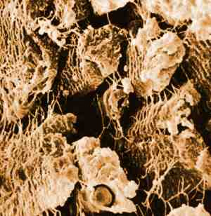
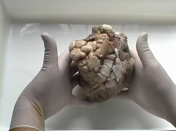
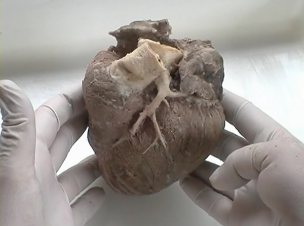
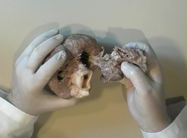
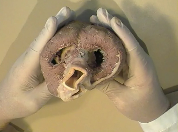
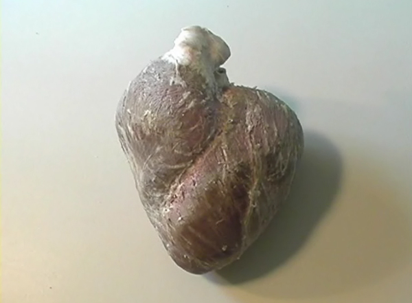
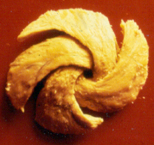
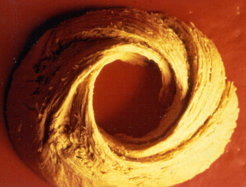
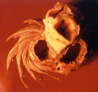
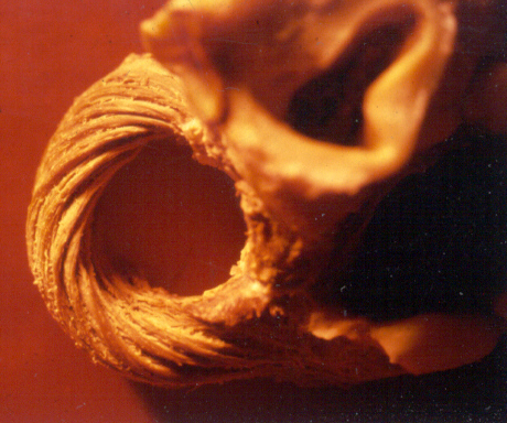
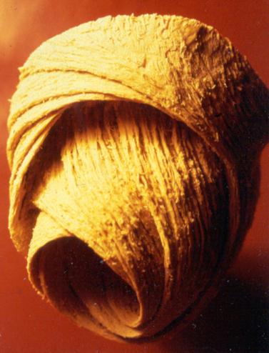
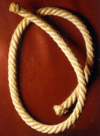
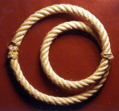
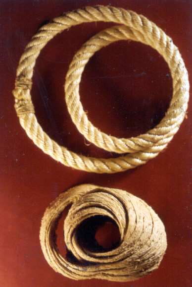
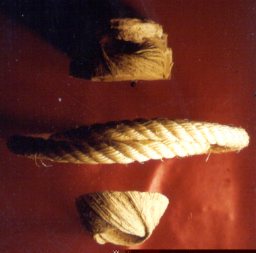
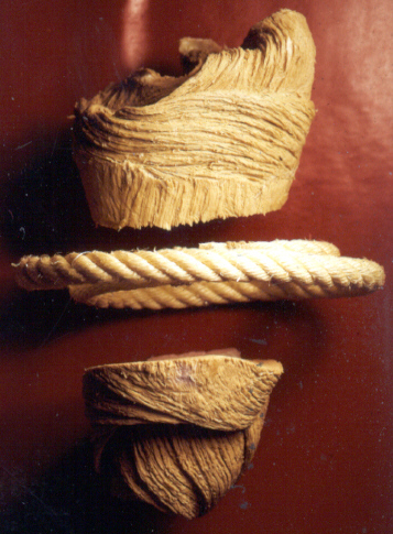
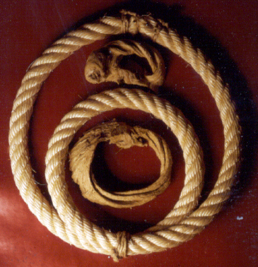
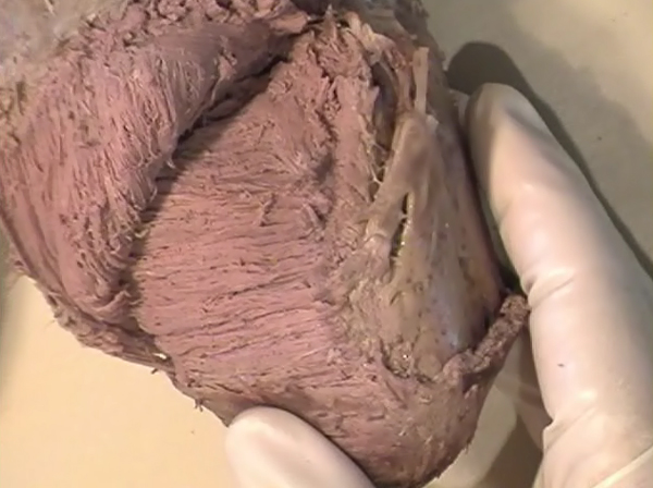
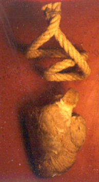
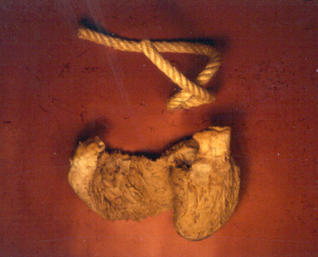
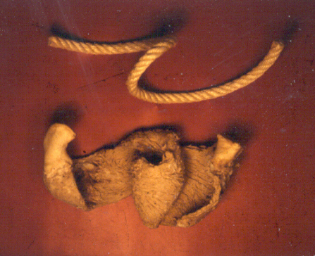
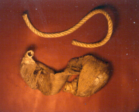
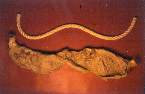
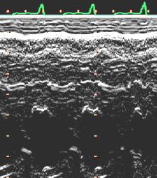
In the ventricular myocardium - size, shape, connections and predominant orientation (in a three-dimensional space) of a single-cell sarcomeral protein molecules, determine their functional behaviour. The same is true for each individual myocardial cell, myocardial fiber (being a series of longitudinally and laterally connected cells), and myocardial laminar sheet. Microscopical and macroscopical myocardial architecture, and particularly the existence of myocardial laminae or fiber bundles, separable by distinct anatomic cleavage planes, have been a controversial subject, since long ago. Ian LeGrice and his associates have documented by their comprehensive, detailed measurements of canine ventricular myocardium, that the myofibers are arranged into distinct myocardial laminae, three to four myocytes thick, separated from adjacent laminae by the extracellular collagen network. The myocytes are tightly coupled within the laminae but sparsely coupled between adjacent laminae. The planes of the laminae could be defined locally by the longitudinal axis of comprising myofibers and by their spiral transmural direction on the ventricular mass level (Figure 4a,b). Today, after more than 50 years spent in painstaking work, I am happy to see that Ventricular Myocardial Band (VMB) has entered the scientific community, and I have to say that I am not surprised with that fact. Simply, because it is natural design, and because of that fact, it suits perfectly it's function. Finally, we all know that form and function in any natural product are inseparable categories. VENTRICULAR MYOCARDIAL BAND - FORMMaterial and methods During this study, more than 1000 hearts, belonging to different species (human, horse, cow, ship, dog, pig, cat, hen, turtle, lizard, fish) were dissected and analyzed. Circulatory system of earth-worms, has been also studied. The hearts were prepared by simple boiling in water (without any additive), in order to loosen the connective tissue. The period of boiling was judged empirically, on the appearance of fibres and depended on the size of the specimen - about 10 minutes or less for a hen heart and up to 2 hours for an adult bovine heart. After boiling, the atria, aorta and pulmonary artery were removed from the heart. The fat from the atrio-ventricular sulci was removed and all visible, superficial coronary vessels excised (Figure 5a,b,c,d,e). Dissection of the myocardial mass was undertaken with non-toothed forceps, scalpel and scissors. Blunt dissection by fingers was generally the most satisfactory way of identifying the direction of the linear (fibre) and laminar (layer) pathways. Gentle longitudinal traction was enough to separate long strips of myocardium, whereas forcible lateral traction tended to tear the muscle fibre. Architectural Basis of Heart Macroscopical StructureA. Four anatomical facts The pattern described was found in all birds and mammals examined, including man. Although the findings relate to human heart, many of the dissections were performed on bovine hearts, which were freely available, but the same morphological features have been amply demonstrated in human hearts as well. Four fundamental anatomical facts are first shown in the order in which they were demonstrated. 1) Left ventricle - apical half The apex of the heart belongs to the left ventricle. Figure 6 illustrates that, starting from the epicardial surface and pulling on any group of superficial fibres, a laminar trajectory is evidenced with a corresponding contingent of myocardium, usually called muscular layer, which always took a helical path. In Figure 7 are evidenced several laminar trajectories, with correspondent muscular layers, running from the periphery to the center. There, the sub-epicardial fibres, undergoing a twist, turned into sub-endocardial fibres around a central tunnel, a virtual one, closed on the outside by the epicardium and on the inside by the endocardium. Another way to demonstrate this arrangement was to dissect an alternate groups of fibres. After we remove the superficial fibres, that virtual tunnel, or the apical orifice, becomes a real one, as seen in Figure 8, defined by the circularly overlapping muscular layers. 2) Left ventricle - basal half A constant architectural order also characterises the arrangement of the fibres in the basal region of the free wall of the left ventricle. There, blunt dissection revealed an indefinite number of laminar trajectories, with their correspondent muscular layers, which took a helical path from the periphery towards the centre (Figure 9). It was similar in structure to that observed in the apex. Similarly, another way to demonstrate this arrangement of circularly overlapping muscular layers, was to dissect an alternate groups of fibres, and expose the grooves defined by the intact adjacent fibres (Figure 10). It could be observed that the majority of fibres are passing beneath, without any insertion for the mitral ring (in Figure 10 the tiny abandoning fibrous structure, commonly denominated as “mitral ring” has been excised). 3) Right ventricle - apical half Dissecting the alternate groups of fibres, in the apical border of the right ventricular free wall, a series of overlapping muscular layers, separated by correspondent laminar trajectories could be seen (Figure 11). 4) Right ventricle - basal half Dissection at the base of the right ventricular free wall, reveals the myocardial arrangement (Figure 12) correspondent to one, previously described in the base of left ventricle and in the apical regions. B. Comment The four anatomical facts described above, shows us that a constant architectural pattern, represented by overlapping or imbricated muscular layers, was common path for both basal and apical myocardium. But, nevertheless, there is a difference between the basal and the apical regions. The fibres belonging to these distinctive regions, in their helical course from the epicardium to the endocardium, run in the opposite sense, as it can be seen, comparing the muscular trajectories at the base and at the apex (Figures 8, 10, 11 and 12). A rope model Observed difference between apical and basal regions could be best explained by the rope model (Figure 13a,b,c). Comparing each one of the segments in the rope model, with the corresponding anatomical preparations (Figure 14a,b,c,d), it can be seen that:
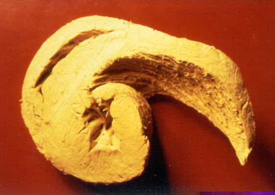
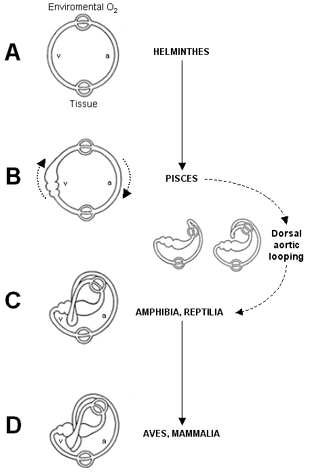
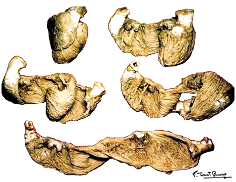
A muscular band hypothesis The above described four anatomical facts and the comparisons with the rope model (Figure 14a,b,c,d), were suggesting a possible secondary structure of the ventricular myocardium. A hypothesis that the ventricular myocardium consists of a single muscular band, twisted on itself and curled in two helical loops, was born. But the principal problem of that conception, was to find the beginning and the end of such muscular band. The beginning and the end of the Ventricular Myocardial Band (VMB) Identification of the beginning and the end of the single ventricular muscle band was, for me, difficult task. After some unsuccessful years of work, I tried to solve this problem going back to phylogenetic studies since, because of the difficulties to obtain foetal hearts, I could not develop any extensive study on ontogeny. Following facts were important for the further development of my research (Figure 15):
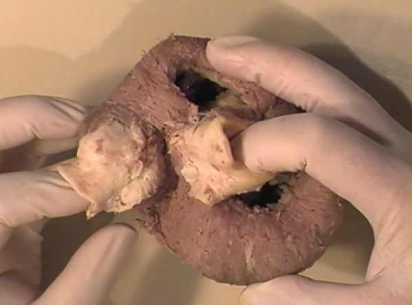
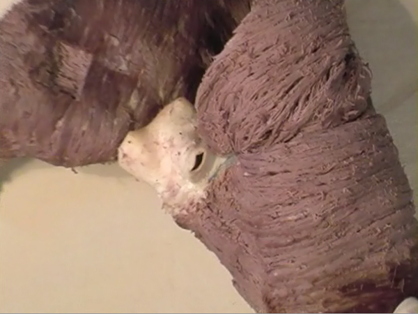
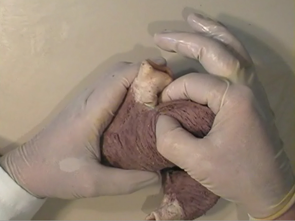
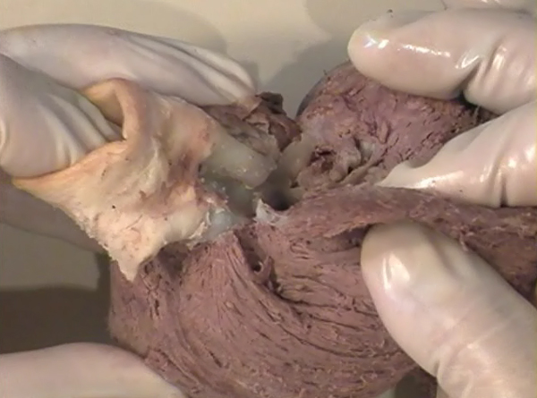
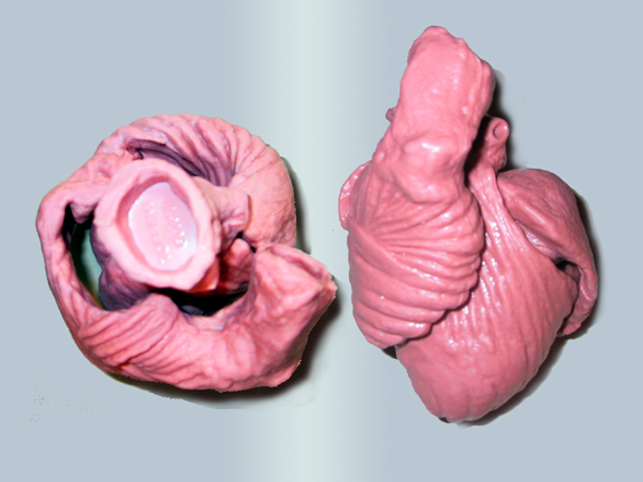
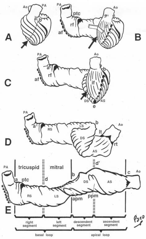
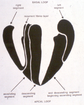
After all, I have concluded that the origin and the end of the ventricular myocardial band, has to be looked for in the roots of the pulmonary artery and the aorta, respectively. Finally, I was able to found them as I have predicted. Further dissections had confirmed that the pulmonary artery was the point of departure of the ventricular myocardial band, whereas the aorta represents it´s final destination. After achieving that results, I realized than the rope model (Figure 13a,b,c) should be transformed in the way shown in (Figure 16). VentRicular Myocardial Band StructureA. The dissection of the band After the separation of the pulmonary artery and the aorta (Figure 17), some superficial fibres (i.e. aberrant fibres), are incised along the anterior interventricular sulcus (Figure 18), to move aside the right ventricular (RV) free wall (Figure 19). By doing so, it is possible to arrive to the posterior limit of the RV cavity, which is represented by the linear bottom of the dihedral angle constituted by the RV free wall and the interventricular septum (Figure 20). The linear posterior limit of the RV cavity has special importance, since it points out the beginning of the laminar trajectory which, when followed, allows us to unroll the VMB. The beginning of this trajectory is exposed by pushing laterally RV free wall (Figure 21). When its pathway is followed, contouring the left ventricle (LV) from it´s posterior side (Figure 22,23), this trajectory leads to the root of the aorta, ending on it’s connection with the left fibrous trigon, which should be then incised (Figures 24,25,26). At this point, we could clearly see that some fibers (i.e. belonging to the descendent segment) are sinking into the LV, making the central fold of the VMB (Figure 27). It is important step to notice, since the trajectory of these fibers, while coming down toward LV posterior wall, are pointing out an important cleavage plan at level of the ventricular septum. Namely, at the level of the interventricular septum, those fibers are crossing the ascendent segment fibers in a 90 degree angle. At this point, we could see this septal crossing from the LV side. Now we should come back, to the site of the posterior limit of the RV cavity. Looking from the RV side, we can see two muscular strata (the deeper belonging to descendent and the superfitial to the ascendent segment), which fibres cross in a 90 degree angle, as described before (Figure 28). The cleavage plan described by these two strata (Figure 29) is the same one, as the cleavage plan that could be seen from the LV side, as described above. The top of the line, defined by those two strata (Figure 30), ends on the aortic root at the point of it’s attachment to the right fibrous trigone. By separating described strata, going in between the vertical (more superfitial, ascendent segment) and the horizontal (deeper, descendent segment) fibres the first thing that we should do is to incise the right fibrous trigone (Figure 30). Now we are able to proceed with the most delicate part of the dissection – dismounting the aorta. Prior to any further description of the dissection method, it is important to emphasize one fact. As it could be seen on the figure (Figure 31a), looking from the atrial side, there are four openings at the ventricular base. But, if we remove the great arteries (aorta and pulmonary artery), it becomes obvious that only three openings are present . In the absence of any muscular structure between the mitral valve and the aorta, there is only one LV opening – aortico-mitral opening (Figure 31b). The aorta is firmly attached to the LV by two fibrous trigones (Figure 31b, marked with black), on which it leans, facing the LV outflow tract. Apart from that, the aortic annulus, which belongs to the right coronary cusp, provides the additional anchorage of the aorta to the septal part of the LV. Fibrous trigones, thus, could be regarded as the “feet of the aorta”. By cutting the aortic attachments with fibrous trigones and those belonging to the right coronary cusp (as described before), it is possible to dismount the aorta from the LV. Since we have already cut both fibrous trigones, we have made a necessary condition to dismount the aorta. By dividing the strata that produce 90 degree septal crossing, we are able to join the same cleavage plan (described before) on the anterior LV wall (Figures 32, 33). The aorta, together with the fibers of the ascendent segment, step by step, as we progress along predominant fiber path, is detached from the rest of the LV mass (Figure 34a). This cleavage plan, encircling it, leads us inside the LV cavity (“The Temple of the Circulatory System”) (Figure 34b). The fingertips, while entering LV cavity, are appearing behind the anterior papillary muscle (in a level of previously mentioned central fold), so that if we continue and close the fist, our fingertips would end between the “Columns of the Temple” - i.e. between anterior and posterior papillary muscle, the former being completely encircled by our hand (Figure 34c). Finally, we came to the most exciting part of the dissection, when the VMB is ready to be stretched out. By simple rotation around its central fold (Figures 34c,d) – it appears in it’s full extent and beauty, with pulmonary artery at one and the aorta at the opposite side (Figure 35). Moreover, by simple inversion of unravelling steps, it is very easy to re-establish, well-known three-dimensional ventricular architecture, just as it was prior to beginning of dissection. There is no other modality of dissection, which is able to accomplish those facts. The result of anatomical studies, giving rise to the VMB concept, provided that simple schema, about which was claiming F.P. Mall, that “applies equally well to all the ventricular myocardial fibres, showing them joined together in a coherent common general architectural plan”. B. The configuration of the ventricular myocardial band Applying previously described method, I was able to conclude that the ventricular myocardium consists of a single muscle band, which starts at the origin of the pulmonary artery and finishes at the root of the aorta. This VMB, twisted two turns on itself in a helical fashion, defines the RV cavity in a half turn, and the LV cavity by the subsequent one and a half turns. In order to make the three-dimensional architectural plan of the ventricular myocardium more clear, it has been reproduced using a paper strip (Figure 36), a rope model with actual VMB (Figure 37a,b,c,d,e) and a silicone rubber mould. A silicone rubber mould of the VMB The first silicone rubber mould of the VMB has been produced in the early 1990’s, from the matrices that I have made using the unravelled bovine hearts. Using the special elastic material (Figure 38) it was possible to reproduce all morphological particularities of the VMB with high fidelity. The value of this model lies in it’s educative capacity, making it possible for all to understand heart structure in a very easy way. So far, this model has been distributed to many people worldwide, and in future, it would be commercially available, along with other very interesting educational tools. C. Segmental anatomy of the VMB 1) The loops The VMB is folded in it’s central part by almost 180 degrees (Figure 39), defining the two loops: the basal loop (from the root of the pulmonary artery to the beginning of the central fold – i.e. to the anterior papillary muscle); and the apical loop (from the beginning of the central fold to the root of the aorta). 2) The segments Each of those two loops could be divided in two segments. The posterior interventricular sulcus, which coincides topographically with the posterior linear border of the RV cavity, divides the basal loop into two segments (Figure 40): the right segment, which consists the free wall of the RV, and the left segment, which consists the free wall of the LV. It is worth to notice here, that the right segment defines the outer (non-septal) border of the tricuspid orifice and the left segment defines the outer (non-septal) border of the mitral orifice. These borders are commonly targeted in AV annuloplastic surgical procedures. The apical loop could be also divided in two segments (Figure 40). After the 180 degree twist (in the central fold of the VMB), the descendant fibres of the apical loop, bend arround the apex and become ascendant fibers. The level of this descendant (subendocardial) to ascendant (subepicardal) turnover, corresponds with the posterior papillary muscle (belonging to the descendant segment), which demarcates the border between the descendent and the ascendent segments of the VMB apical loop. These two segments constitute the interventricular septum. 3) The interventricular septum The interventricular septum is very interesting (and controversial) structure (Figure 41), and will be now explained separately. As explained earlier and in the lines above, the interventricular septum is formed by 90 degree crossing of the apical loop segments (i.e. descendent and ascendent). This “bilayered” structure of the interventricular septum (Figure 42a,b) is commonly seen on M-mode echocardiographic and histological examinations, although, no one could explain a 90 degree angle between these two layers. In a reality, and as some other M-mode and histological findings are suggesting, the interventricular septum is, in fact, “three-layered” structure (Figure 43a,b). This is due to the fact, that the interventricular septum actually incorporates the third (although tiny) component of fibres. These fibers, coming from the free wall of the RV, reflect at the anterior interventricular sulcus, and become subendocardial, ascending toward the pulmonary artery ring, pulmo-tricuspid chord and tricuspid ring, where they finish with insertion. The existence of these recurrent fibers (Figure 41) is very interesting, in a light of phylogeny and some ongoing explanations of the “sphincteric function” of the RV outflow tract. Also, these fibers may explain some controversies about the sequence of spontaneous electrical activation, as well as those concerning the optimal site for the permanent pacing electrode. SUMMARY Anatomy (until this world becomes completely digitalized) could be learned only by dissections. The words of Leonardo daVinci are still valid today. But, unlike some contemporary scientists think, to cut something, does not necessarily need to destroy the meaning of it. To cut “by brain” is not the same as to cut by knife. Described methodology, applied in the anatomical dissections of the VMB (I humbly believe), was respecting the rule based arrangements of the ventricular myocardial fibers, and thus, the results explained here, are not “artificial facts” but natural reality. It is shown that the architectural organization plan of the ventricular myocardial fibers configurate a muscular band. This VMB describes two spirals in the space, during its trajectory from the pulmonary artery to the aorta, defining a helicoid which delimitates two cavities, the RV and the LV cavity. In relation to their location, the first spiral is designated as the basal loop and the second one as the apical loop. In both loops, one could distinguish two segments. In the basal loop - the right segment, which corresponds to the RV free wall; and the left segment, which participate in constitution of the LV free wall. In the apical loop - the descendent segment, with fibers coming down from the ventricular base to the apex; and the ascendant segment with fibers going up from the apical regions to the basal ones (Figure 44). The evidence of the VMB has revealed unavoidable coherence and mutual coupling of form and function in the ventricular myocardium, making it possible to understand the principles governing developmental, electrical, mechanical and energetical events within the human heart. I am aware that any unresolved problem in medical (or any other) science, automatically becomes the unique kind of Rorschach’s test. Structure and function of the ventricular myocardium is, perhaps, the best example for the previous statement. This problem has gathered (or divided) numerous experts, from different branches. Today, it is not unusual to find that mathematician and cardiac surgeon talk about the heart in a very comprehensive manner. Paradoxically, even so, a coherent explanations of some very simple questions are still pending. It is upon us to see why, but it is unavoidable fact that the nature is not so complicated as the scientist are. |
|||
|
Figure 1. |
||||
|
Figure 2. |
||||
|
Figure 3. |
||||
|
Figure 4a. |
||||
|
Figure 4b. |
||||
|
Figure 5a. |
||||
|
Figure 5b. |
||||
|
Figure 5c. |
||||
|
Figure 5d. |
||||
|
Figure 5e. |
||||
|
Figure 6. |
||||
|
Figure 7. |
||||
|
Figure 8. |
||||
|
Figure 9. |
||||
|
Figure 10. |
||||
|
Figure 11. |
||||
|
Figure 12. |
||||
|
Figure 13a. |
||||
|
Figure 13b. |
||||
|
Figure 13c. |
||||
|
Figure 14a. |
||||
|
Figure 14b. |
||||
|
Figure 14c. |
||||
|
Figure 14d. |
||||
|
Figure 15. |
||||
|
Figure 16. |
||||
|
Figure 17. |
||||
|
Figure 18. |
||||
|
Figure 19. |
||||
|
Figure 20. |
||||
|
Figure 21. |
||||
|
Figure 22. |
||||
|
Figure 23. |
||||
|
Figure 24. |
||||
|
Figure 25. |
||||
|
Figure 26. |
||||
|
Figure 27. |
||||
|
Figure 28. |
||||
|
Figure 29. |
||||
|
Figure 30. |
||||
|
Figure 31a. |
||||
|
Figure 31b. |
||||
|
Figure 32. |
||||
|
Figure 33. |
||||
|
Figure 34a. |
||||
|
Figure 34b. |
||||
|
Figure 34c. |
||||
|
Figure 34d. |
||||
|
Figure 35. |
||||
|
Figure 36. |
||||
|
Figure 37a. |
||||
|
Figure 37b. |
||||
|
Figure 37c. |
||||
|
Figure 37d. |
||||
|
Figure 37e. |
||||
|
Figure 38. |
||||
|
Figure 39. |
||||
|
Figure 40. |
||||
|
Figure 41. |
||||
|
Figure 42a. |
||||
|
Figure 42b. |
||||
|
Figure 43a. |
||||
|
Figure 43b. |
||||
|
Figure 44. |
||||
|
||||